Cross Resonance Gate#
The Cross-Resonance (CR) gate is one of the most widely used two-qubit entangling gates for superconducting qubits. By using only microwave controls, they eliminate the need for flux-tunable qubits, thus avoiding noisy flux lines.
The gate acts on pairs of qubits that are either capacitively coupled or connected by a coupler. In its most basic form, it applies a pulse to the control qubits at the frequencies of the target qubits. Additional single-qubit pulses can be incorporated to enhance performance, but the core mechanism relies on this principle.
Let’s see why that works by looking at the driving Hamiltonians of two qubits (ref [1]):
With:
Where \(g\) is the coupling, \(\Delta_{12}\) is the frequency difference between qubit 1 and qubit 2 and \(\Omega V_{di}(t)\) is the driving for qubit i. If we drive qubit 1 at the frequency of qubit 2, based on the equation for \(H_{d,2}\) it will result in a combination of \(\nu_2^{+} \sigma_x\otimes \mathbb{1}\) and \(\mu_1^{-} \sigma_z \otimes \sigma_x\) This means that the Rabi oscillations of qubit 2 will have a frequency given by:
where \(z_1 = \langle \sigma_z \mathbb{1} \rangle\) , and \(z_1\) depends on the state of qubit 1, therefore demonstrating the existence of the coupling between the two qubits.
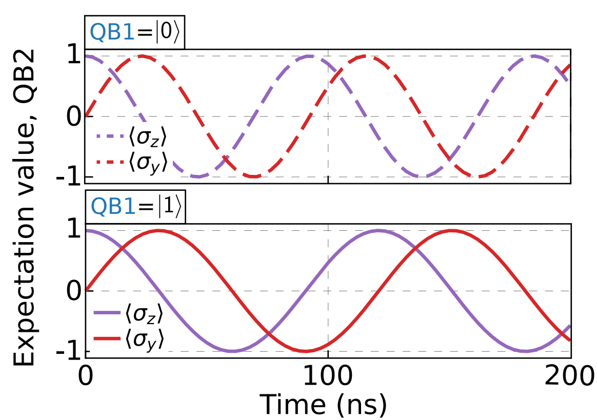
Lets now explain how the tuneup process works. The CR gate consists of pulsing the control qubit with a drive tone at the frequency of the target qubit. By varying either the amplitude or the duration of the tone, we observe the target qubit undergoing Rabi oscillations. To tune-up the gate, we want to meet the following condition: if the control qubit is in the zero state, nothing should happen to the target qubit. If the control qubit is in the excited state, the target qubit should undergo a full pi rotation about the X axis as shown in the picture above (see p.37, ref [1]).
We thus seek an amplitude (or duration) at which both conditions hold approximately to the best degree possible.
Let’s walk through the steps to perform this experiment on Keysight hardware using
the QCS package.
First, we’ll load all the necessary packages and a channel mapper, which links up to
the hardware channels. If a channel mapper doesn’t exist, we can create a new one and
add the hardware references to it. Then we generate a calibration set for the qubits
using make_calibration_set(). This file that stores
all the important variables and parameters we need to run experiments on our quantum
system. We also import an experiment with simulated data
to demonstrate the fitting and calibration workflow at the end of this file.
[2]:
import numpy as np
import keysight.qcs as qcs
from keysight.qcs.experiments import make_calibration_set
from keysight.qcs.experiments import CrossResonance
from simulated_experiments.simulated_experiments import SimulatedCRExperiment
[3]:
# Set this to True if channel mapper exists
channel_mapper_exists = False
if channel_mapper_exists:
mapper = qcs.load("<path/to/channel_mapper.qcs>")
else:
# generate an empty channel mapper with the correct address
mapper = qcs.ChannelMapper("127.0.0.1")
The CR gate is a two-qubit experiment and therefore requires defining the targets
a bit differently than for the single-qubit experiments. Here we are doing a minimal
example of 1 CR gate between qubit 0 and qubit 1, where the former is the control and
the latter is the target.
To this end, we describe the connections as a list of tuples where the control
qubit is specified first in edge_list and then
make a MultiQudits object out of it using the
make_connectivity() method.
The obtained mq_targets is then the equivalent
of qubits for other 1 qubit experiments. We can then simply pass it to our
built-in CrossResonance,
which then acts on the given connectivity encoded in this mq_targets.
Note that the CalibrationSet object provided to
the experiment class must match
the connectivity, as it stores the linker definition for the CR gate. This is why
we can pass the edge_list
to make_calibration_set(), which will
automatically handle this for us.
Note
It is also possible to define the
CalibrationSet on a longer list of
edges (e.g., [(0, 1), (1, 0)]) and only run the Cross Resonance calibration on one
of these directed edges (e.g., [(0, 1)]), as long as there’s at least one matching
edge.
[4]:
n_qubits = 2
qubits = qcs.Qudits(range(n_qubits))
edge_list = [(0, 1)]
mq_targets = qubits.make_connectivity(edge_list)
calibration_set = make_calibration_set(n_qubits, edge_list)
# Set this to True if connected to hardware
run_on_hw = False
Next, we’ll set up our Cross Resonance experiment to find the amplitude
of the CR gate. The
CrossResonance
class is
actually a subclass of the more general
CalibrationExperiment.
which is specifically designed to calibrate quantum
operations and store all the parameters in the
CalibrationSet.
In this example, we’re setting up the experiment to calibrate the amplitude for 1 CR gate.
[5]:
# Create a resonator spectroscopy experiment
cross_resonance = CrossResonance(
backend=mapper,
calibration_set=calibration_set,
qubits=mq_targets,
operation="CR",
)
[6]:
# Draw the program to view the hardware operations
cross_resonance.draw()
|
Program
|
||||||||||||||||||||||||||||||||||||||||||||||||||||||||||
|
||||||||||||||||||||||||||||||||||||||||||||||||||||||||||
Now we specify the amplitude range to sweep over for the CR pulse.
You can simply pass it as an argument to the
CrossResonance class.
Note
If the “CR” operation is stored in the
CalibrationSet under a
different name, you’ll need to pass that name as an argument (operation=<name>)
to the CrossResonance class so it can
reference the correct entry in the
CalibrationSet.
[7]:
# Retrieve the amplitude stored in the calibration set
current_freq = cross_resonance.calibration_set.variables.cr_gate_amplitude.value
# Set the frequency range for sweeping
start = 0
end = 0.5
nsteps = 10
freq_scan_values = np.linspace(start, end, nsteps)
[8]:
# Configure the repetitions for this experiment
cross_resonance.configure_repetitions(
n_shots=1, cr_amplitudes=freq_scan_values, hw_sweep=False
)
To execute this experiment, we can simply run
[9]:
if run_on_hw:
cross_resonance.execute()
else:
# load in a previously executed version of this experiment
cross_resonance = qcs.load("CrossResonance.qcs")
For the purposes of this demonstration, we added an “ancilla” qubit to the program and connected the physical output channels for our CR control qubit’s control line to the digizer associated with the ancilla to allow us to capture the CR pulse.
[10]:
# Plot the trace waveforms
cross_resonance.plot_trace()
Fitting and calibration workflow#
Let’s walk through how to extract the desired CR drive amplitude and how to update the corresponding variables in our calibration set. For this example, we load in an experiment with simulated data that we imported at the beginning of the file:
[11]:
cross_resonance = SimulatedCRExperiment(mapper, calibration_set, mq_targets)
The fit() method retrieves I/Q data
acquired while sweeping cr_gate_amplitude, for both control qubit states — ground
and excited, and fits them to a decaying sinusoidal model, as specified by the
built-in DecayingSinusoid.
The result of the fit is an EstimateCollection,
which contains individual Estimate objects.
Each estimate corresponds to a specific qubit and control pulse amplitude.
Here, the first two estimates represent the fitted parameters for qubits 0 and 1
at a control pulse amplitude of 0, while the last two correspond to qubits 0 and 1
at a control pulse amplitude of pi.
[12]:
ec = cross_resonance.fit()
print(ec.estimates)
[Estimate(amplitude=1.0, decay_rate=1.0, frequency=40.0, phase=-1.5707963267948968, ...), Estimate(amplitude=1.0, decay_rate=1.0, frequency=40.0, phase=-1.5707963267948968, ...), Estimate(amplitude=1.0, decay_rate=1.0000000000000002, frequency=40.0, phase=1.5707963267948966, ...), Estimate(amplitude=1.0, decay_rate=1.0000000000000002, frequency=40.0, phase=1.5707963267948966, ...)]
The fitted and the pre-processed data can be visualized by calling the
plot() method:
[13]:
cross_resonance.plot()
We can then get the calibration value associated to this CR Experiment by
calling
get_updated_calibration_values().
This method computes the cr_gate_amplitude for which we have the first maximum
separation between the ground and excited state responses — indicating the point of
highest contrast and the optimal CR gate amplitude
[14]:
cross_resonance.get_updated_calibration_values()
[14]:
{'cr_gate_amplitude': [0.04040404040404041]}
To check the current state of that variable in the calibration_set to confirm its update, one can do:
[15]:
cross_resonance.calibration_set.variables.cr_gate_amplitude.value
[15]:
array([0.2])
The update is then done as follows:
[16]:
cross_resonance.set_updated_calibration_values()
cross_resonance.calibration_set.variables.cr_gate_amplitude.value
[16]:
array([0.04040404])
The last line printing the new updated value, thus confirming that the update has been successful.